Mauser C96 Broomhandle · Volume 6
Mechanics, Dimensions & Drawings
The prop-up short-recoil action, the no-pin takedown, and the dimensioned-drawing / CAD source package
Contents
This volume is the technical heart for a builder: how the action actually works, how it comes apart (and the order matters), and what dimensioned geometry is available to work from. It pairs the public-domain patent drawings (Vol 2) with the dimensional sources cataloged in ../blueprints/README.md.
6.1 The action: “prop-up” short recoil
The C96 is the textbook example of “prop-up” locking: the bolt is locked to the barrel by a separate locking block whose lugs are not integral to the barrel and which can pivot out of engagement. The whole barrel assembly recoils a short distance.
The cycle, step by step:
- Trigger → the sear actuator lifts the sear lever, the sear nose releases the hammer, and the hammer falls onto the firing pin.
- Firing → chamber pressure drives the bolt rearward; bolt and barrel-extension are still locked together (locking-block lugs engaged), so the whole barrel assembly recoils a short distance.
- Unlocking → the locking block’s forward tooth bears on the C-shaped coupling rocker, compressing the mainspring (which lies in the lock sub-frame at ~30° with two plungers). The block pivots about its loose attachment to the barrel extension; its lugs drop out of the recesses in the bolt underside. Barrel assembly stops.
- Bolt runs back on its momentum, compressing its recoil spring and cocking the hammer; the spent case, held by the extractor, strikes the ejector (the upward projection at the front of the lock sub-frame) and is thrown clear.
- Return → the bolt’s recoil spring drives it forward, stripping and chambering the top cartridge; the locking block swings up and forward, lugs re-engage, and the gun is back in battery.
6.2 The disconnector — why it’s semi-auto (build-critical)
During recoil, the underside projection of the forward mainspring guide bears on the sear actuator and disconnects the trigger from the sear, so the sear re-catches the cocked hammer instead of letting it follow the bolt home. The earliest C96s lacked this projection — and would fire full-auto if the trigger wasn’t released crisply. For any semi-automatic reproduction (Vol 9) the disconnector geometry is mandatory: reproduce the forward-guide projection and the sear-actuator interface exactly.
6.3 Takedown — a sequence, not a disassembly
The C96 has no assembly pins and one screw (Vol 2), so it does not “disassemble” so much as un-interlock in a specific order. Forcing the wrong step damages parts. The field-strip outline (consistent across the standard published manuals; describe and follow a proper reference on the bench):
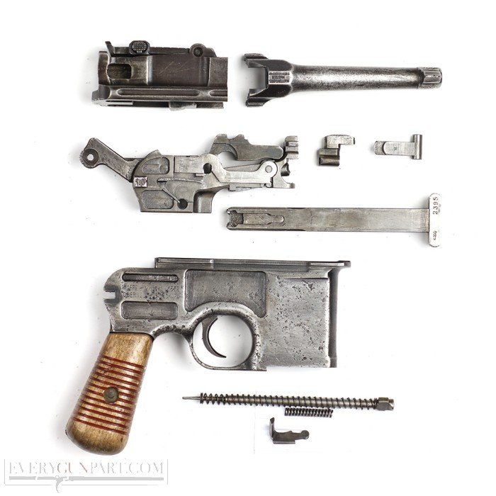
- Magazine floorplate — depress the plunger with a tool/cartridge tip, slide the floorplate forward, lift off; remove the spring and follower.
- Cock the hammer — the hammer body is machined so the takedown latch cannot rise unless the hammer is cocked (Vol 2 §2.6). Raise the latch (rear of receiver, below the hammer pivot) to unlock the barrel assembly.
- Draw the barrel + barrel-extension assembly rearward out of the receiver. The lock sub-frame comes with it, loosely clawed underneath by the locking block’s forward hook.
- Lower / detach the lock sub-frame from the barrel extension (it’s just hooked on); lift off the locking block from its retaining stud.
- Firing pin — depress, quarter-turn, release (it springs out with its spring); on very early guns it’s held by a dovetailed flat plate instead.
- Bolt — remove the bolt stop through the rectangular slot in the right side of the barrel extension, then withdraw the bolt and its recoil spring.
Reassembly reverses this, with the well-known gotcha that the coupling rocker must be seated correctly (“nose” forward, axle ends seated) before the lock sub-frame is forced back into the receiver — get it wrong and the frame is very hard to remove again. The mainspring is under tension even at rest, so clamp the frame in a padded vise for the spring/rocker steps.
Safety (Vol 2 §2.6): the action loads from the rear; the takedown-latch + hammer interlock exists so a latch failure can’t launch the mechanism into the shooter. On a reproduction, this interlock is not optional.
6.4 The safety mechanisms (by era)
The thumb safety at the left rear evolved (a dating handle, Vol 4–5): long lever (early; pushed down to apply) → late first type → “Ns” New Safety (~serial 200k; requires drawing the cocked hammer back slightly before applying) → Universal Safety (M30; can lower the hammer safely on a loaded chamber, blocks the hammer via the safety-lever pivot profile). A reproduction should pick one era’s safety and build it consistently with the rest of the feature set.
6.5 Dimensions — what’s known
Envelope and key figures (verify before machining; full table + sources in ../blueprints/README.md):
| Dimension | Value | Note |
|---|---|---|
| Overall length (5.5″ standard) | 312 mm (12.3 in) | |
| Overall length (Bolo) | 271 mm (10.7 in) | |
| Barrel — standard | 140 mm (5.5 in) | also 4.75″/4″/5.25″ by era; Bolo 3.9″ |
| Weight | ~1.13 kg (2 lb 8 oz) | one of the heaviest service pistols |
| Bore (7.63) | .3008 in | 9 mm build → .355 in (Vol 3) |
| Rifling | 4-groove RH early; 6-groove RH from ~40k | 9×19 build: 6-groove .355 |
| Peak pressure (7.63) | ~30,000 psi | 9×19 ~35,000 psi standard |
These are envelope/operational figures. Part-level dimensioned geometry does not exist publicly (Vol 6 §6.6) — it has to come from the patent (geometry/kinematics), the published exploded diagrams, and ultimately a measured specimen.
6.6 The drawing & CAD source package
The full, graded catalog lives in ../blueprints/README.md. Summary of what a builder actually works from:
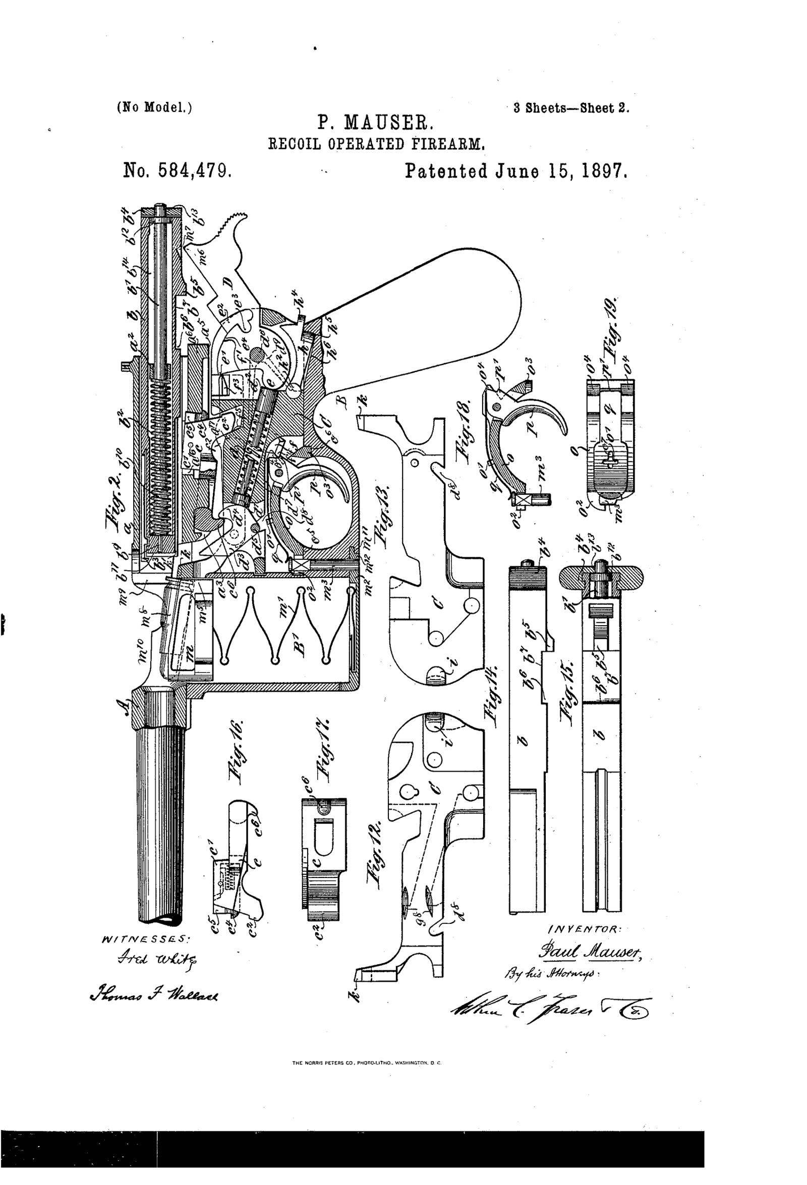
- Patent drawings (public domain, in
../blueprints/) — US 584,479 (base) gives authoritative mechanism geometry and kinematics across 3 sheets (Figs 2.1, 2.2, 6.1); the Schnellfeuer patents are reference-only. Schematic, not toleranced. - Reverse-engineered solid CAD (STEP/IGES) — community models (GrabCAD/Cults3D) that import into Fusion 360 for measuring/editing; accuracy varies, verify against the patent + a specimen. (Note: the one community SLDPRT obtained for this project did not yield a usable C96 on export — see
../blueprints/README.md.) - Published exploded/sectioned diagrams — in the collector literature (
../references/). - A measured specimen — the ground truth for part-level dimensions, and the realistic source for the lockwork.
Practical workflow: treat the patent as the geometry/kinematics reference, build the part models in Fusion against it, lock the chamber/barrel for 9×19 (Vol 3), and measure a real specimen for the lockwork tolerances before cutting steel (Vol 9).
6.7 References (Vol 6)
- US Patent 584,479 (P. Mauser, 1897) — public domain;
../blueprints/. - Henrotin, The Mauser C96 Explained (©2002) — facts only; standard C96 field-strip manuals.
../blueprints/README.md(drawing/CAD catalog);../volume_sources/research_notes.md§1–2.- Full bibliography: Vol 12.