The Blanchard Lathe · Volume 3
How It Works
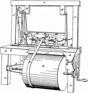
This is the volume that earns the series. Everything else — the biography, the licensing empire, the historiography — orbits one genuinely clever mechanism, and the goal here is to describe it precisely enough that you could lay out the linkage on a napkin and know it would work. The clearest primary-flavor description survives near-verbatim across the 1912 Iles biography and other accounts; the reconstruction below is that description, translated into the terms a machinist actually thinks in.12
3.1 The One-Sentence Version
A finished master model and an oversized wooden blank are mounted on a common, slowly-rotating shaft system and turn together in unison. A hard tracer (friction) wheel rides the model’s surface; a fast-spinning cutter wheel, rigidly linked to the tracer on a pivoted swing frame, cuts the blank. As the model’s contour pushes the tracer in and out, the swing frame rocks, and the cutter — at a fixed offset on that same frame — is forced to the identical radial position, reproducing the contour in the wood. A carriage traverses the whole assembly along the length of the work, so the entire stock is profiled as a dense series of radial cuts. The model is the program.
3.2 The Elements, One at a Time
Common rotating axle. The model and the blank sit on parallel spindles driven off the same shaft, so they rotate together, slowly, and in phase — synchronized by gearing or belting, not turning independently. Phase matters: the model’s muzzle-end at twelve o’clock must correspond to the blank’s muzzle-end at twelve o’clock, or the copy is clocked wrong relative to the master. The model was originally an iron master pattern, cast or machined to the exact finished stock contour; later shops sometimes used wood or metal masters.
The two wheels, “of like diameter, about three feet apart.” The tracer wheel is small, hard, and shaped to ride into every contour of the model — it is a follower, doing no cutting. The cutter wheel carries, in the period phrase, “a score of sharp cutters” on its rim and spins fast to hog wood out of the blank. The ~3-foot spacing is not arbitrary: it is roughly the length of a musket stock, so that the tracer works one end of the model while the cutter works the corresponding station of the blank. Equal diameter on a simple pivoted linkage is what gives the 1:1 copy (see the ratio note below).
The pivoted swing frame. Both wheels are carried on a single frame that can rock through a wide arc about a pivot. When the model’s surface is fat (the butt), it pushes the tracer outward and swings the frame one way; when the surface is thin (the wrist), the tracer falls inward and the frame swings back. Because the cutter is bolted to that same frame at a fixed offset, whatever radial position the model forces on the frame is reproduced identically at the cutter. The frame is the mechanical link that turns “what the tracer feels” into “where the cutter cuts.”
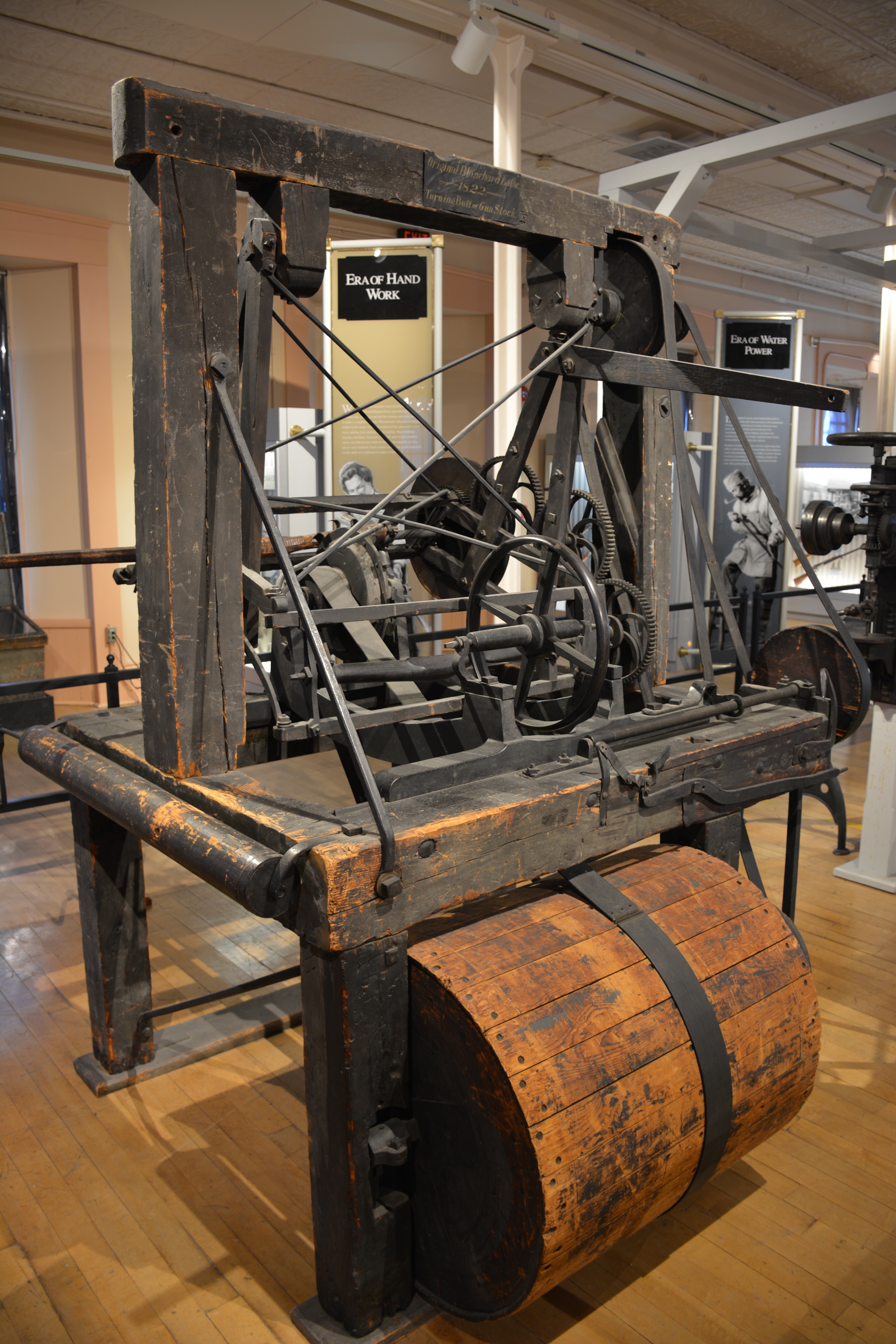
The traversing carriage. The frame rides a carriage that feeds longitudinally from one end of the work to the other, so the machine profiles the entire length — not one cross-section but a continuous series of closely-spaced radial cuts, effectively scanning the model and printing the same scan onto the blank.
3.3 Why This Makes Any Irregular Shape (and a Plain Lathe Can’t)
Here is the crux, and it is worth being exact because it is the whole reason the machine exists.
On an ordinary lathe, the cutting tool’s distance from the axis is set by the operator and does not depend on the rotational angle of the work. Whatever comes off is therefore symmetric about the axis — a surface of revolution. There is no mechanism by which the tool “knows” it should be deeper at ten o’clock than at two o’clock, so it can’t be.
Blanchard’s machine couples the cutter’s radial position, in real time, to the angular position of the model through physical contact. The tracer is literally shoved in and out by the model’s real surface as the model spins, and the cutter mirrors that motion. So the depth of cut varies with rotational angle exactly as needed to reproduce a lopsided cross-section. Feed that behavior down the length via the carriage and you can reproduce any irregular, non-symmetric solid the tracer can physically ride over. A gunstock — flat lock-panel, curved comb, offset wrist, flared butt — is precisely such a solid, and it is why this was the machine that finally took stock-shaping off the bench.
The mechanism has no stored notion of “gunstock.” It copies whatever master you hang on it. That generality is the same generality your CNC controller has: swap the model (or the CAD file) and you make a different thing on the same machine.
3.4 The Copy Ratio — Say What We Actually Know
The period description (equal-diameter wheels, rigidly linked, on one pivoted frame) implies a 1:1 transfer between tracer motion and cutter motion — the machine copies the master at full size. This series treats the 1:1 ratio as *inferred from the mechanism description, not directly sourced.1 A true adjustable-ratio pantograph linkage (as in engraving machines going back to Nartov’s 18th-century ornamental lathe, and in later commercial engravers) can enlarge or reduce by relocating a pivot along the linkage arms — but no evidence was found that Blanchard’s 1819/1822 gunstock lathe had adjustable-ratio linkage, and the safe assumption is that it did not. Later 19th-century copying lathes in other trades did sometimes use true pantograph linkages for scaling; that is a related but distinct lineage, not Blanchard’s gunstock machine. If you build a demonstrator, build it 1:1 unless a direct reading of the patent sheets tells you otherwise.
3.5 Cut Quality and the “It’s Really a Shaper” Point
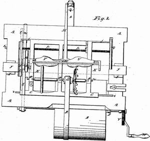
A rotating multi-blade cutter wheel fed along the work takes a series of discrete “bites,” so it leaves a rippled, faceted surface — a near-net roughing result, not a finish. NPS states it plainly: “The lathe left rough ridges requiring subsequent hand finishing with scrapers and sandpaper.”3 This is the same near-net-then-hand-finish reality your ballnose roughing gives you, and it is why the stocking line (Volume 4) sent turned stocks straight into hand finishing before the inletting machines.
The NPS also makes a terminology point worth repeating: the device is “technically a shaper since the cutter is a rotating wheel rather than a true lathe.”4 Calling it a “lathe” is convention, not strict accuracy — the workpiece rotates like lathe work, but the material is removed by a rotating multi-tooth cutter, shaper-style, not a single fixed point.
3.6 Drive: Water, Line Shaft, Belts
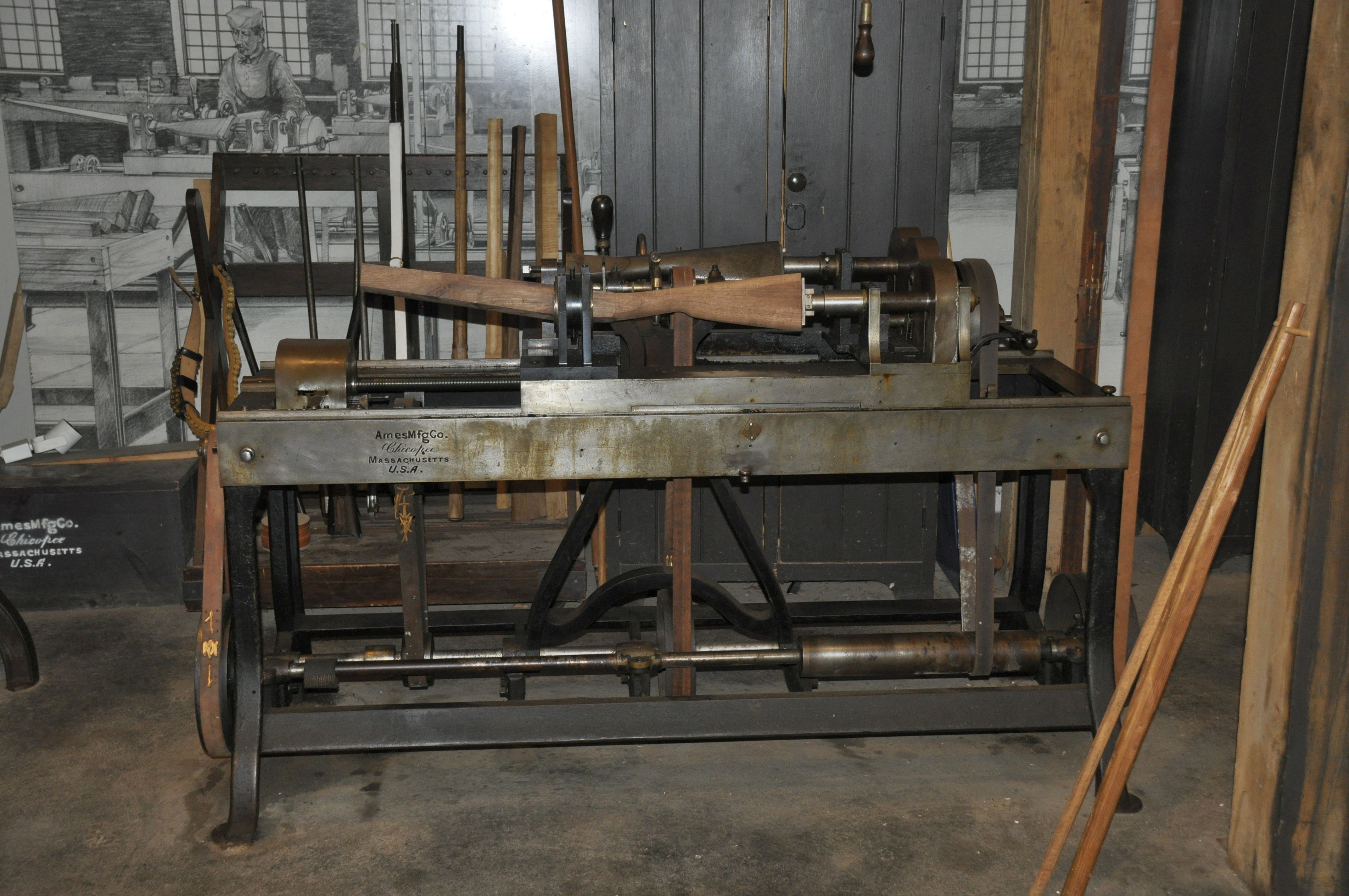
Armory installations were line-shaft driven, ultimately from water power. The surviving Harpers Ferry example (a later-generation machine, 1850s) is documented as “water-powered via pulleys and leather belts.”5 By the 1850s, Springfield machinist Cyrus Buckland had built an improved, more compact iron-framed version of the machine.3 The two rotational rates are very different in character: the model/blank shaft turns slowly (you want many closely-spaced cuts per unit length as the carriage creeps along), while the cutter wheel turns fast (surface speed for a clean-ish wood cut). Getting both off one water-driven line shaft is a matter of pulley ratios — exactly the belt-and-pulley reasoning a period millwright lived in.
3.7 Feeds, Speeds, Depth of Cut — the Honest Gap
No source consulted gives quantitative period feeds, spindle RPM, or depth-of-cut figures for the original machine. The period accounts are narrative, not engineering specs, and this appears to be genuinely hard-to-find data — it would likely require primary Springfield ordnance/manufacturing records or a dimensional reading of the patent sheets. This series will not invent numbers. Where Volume 8 needs to talk about passes, it reasons from the mechanism (a slow work rotation, a fast cutter, one-or-few roughing passes leaving ridges) and labels it as reasoning, not as sourced fact. If you build one, you will be dialing pulley ratios and feed by feel and by the tear-out the wood gives you — which, honestly, is what a period operator did too.
3.8 Bibliography
Footnotes
-
George Iles, Leading American Inventors (1912) — source of the “on an axle slowly revolved… two wheels of like diameter, about three feet apart” mechanical description. Secondary, somewhat romanticized. ↩ ↩2
-
ASME, “Thomas Blanchard’s Manufacturing Impact.” https://www.asme.org/topics-resources/content/thomas-blanchard ↩
-
NPS, Springfield Armory NHS, “Woodworking at Springfield Armory.” https://www.nps.gov/spar/learn/historyculture/sa-woodworking.htm ↩ ↩2
-
NPS, Springfield Armory NHS, “Thomas Blanchard and His Lathe.” https://www.nps.gov/spar/learn/historyculture/thomas-blanchard-and-his-lathe.htm ↩
-
Wikimedia Commons, File:Harpers_Ferry_gun_smith_shop_-Blanchard_lathe-_01.jpg (Jarek Tuszynski, CC BY 4.0) — describes the machine as water-powered via pulleys and leather belts. ↩
Comments (0)