Types of Scopes · Volume 8
Mounting, Zeroing & Maintenance
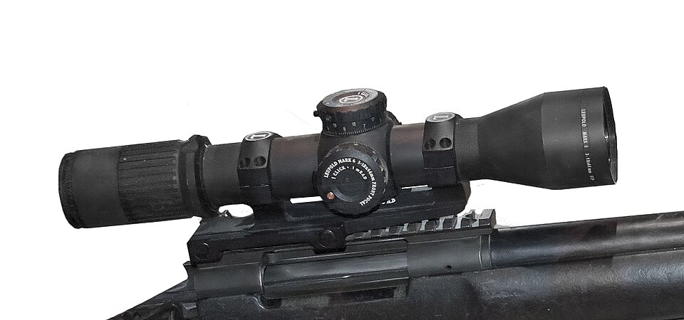
A scope is only as honest as its mount. The finest glass and the best-tracking erector in the world will wander if the rings are misaligned, the base is under-torqued, or the reticle is canted — and every one of those faults masquerades as a scope defect. This volume is the bench workflow: rings and bases, the torque question, lapping, cant, the 20 MOA rail, bore-sighting, zeroing, and the two tests that prove a scope actually tracks.
8.1 Rings and Bases
One-piece mounts pre-align the ring bores at manufacture (minimizing tube stress) and span more of the receiver — four or five inches, four screws — for rigidity, at the cost of weight, price, and the need for a full unbroken rail. Two-piece mounts are lighter and clear the ejection and loading port (often the only option on top-loaders, break-opens, and interrupted-rail levers), but their separately-installed rings more often benefit from lapping.1
Know your rail geometry. Picatinny / MIL-STD-1913 slots are 0.206 in wide, spaced 0.394 in center-to-center, 0.118 in deep, with square flat-bottom recesses. Weaver slots are narrower (~0.180 in) with no standardized spacing and rounded bottoms. The compatibility is asymmetric: Weaver-pattern rings generally fit a Picatinny rail, but true Picatinny mounts do not reliably fit a Weaver base.2 And the ring ID must match the tube OD (1 in / 30 / 34 / 35 mm) exactly — an oversized ring lets the scope shift under recoil; an undersized or misaligned one crushes the tube.
8.2 The Torque Question
There is no universal torque value, and pretending otherwise damages scopes. Defer to the specific ring and base maker’s spec; the guidance below is a range to sanity-check against, not a substitute.
- Ring cap screws (ring-to-tube): a consensus range of roughly 15–25 in-lb, with modern thin-tube scopes trending to the low end (15–18). Per-brand figures vary widely — from ~15 (Badger, Leupold) up to 25 (Nightforce, Warne) and an outlier 35 (Barrett Zero Gap), which is exactly why you check the spec.
- Base/rail screws (base-to-receiver): generally higher and swinging widely by mount, roughly 25–68 in-lb. But there is a separate constraint — receiver material: steel tolerates ~25 in-lb, aluminum ~15 in-lb. Do not average the two sets: the mount spec answers “what the hardware wants,” the material limit answers “what the threads survive,” and the lower of the two wins.3
Use a calibrated inch-pound wrench and thread locker where the maker specifies it. All torque figures in this hub are ranges by design — the manufacturer’s number is the only authoritative one.
8.3 Lapping
Misaligned ring bores point-load the tube, causing erector binding (and potential erector damage) and point-of-impact shift or lost zero under recoil. (Note: sources support tube-crush, erector-bind, and POI shift — not an outright cracked or fractured tube; frame it that way.) The fix is to verify alignment with alignment rods, then run a steel lapping bar with abrasive compound (aluminum oxide cleans up easier than silicon carbide), back-and-forth with rotation and even pressure, until roughly 75% contact shows on the bores. Optional for plinking; common practice for precision.4
8.4 Cant and the Scope Level
Canting — rolling the rifle about the bore axis — misaligns the elevation axis from true vertical, so dialed elevation moves the reticle along a tilted axis: part of the intended vertical drop compensation resolves into a horizontal component (a lateral miss) while the vertical component (∝ cos θ) slightly under-compensates. The error grows with both cant angle and elevation dialed — which means with range. Worked figures: a .270 Win at 300 yd with 5° of cant throws ~2.5 in horizontal; 3° of rifle cant at 1,000 yd throws roughly 24 in horizontal with negligible vertical change.5 An anti-cant level — bubble or electronic — keeps the elevation axis plumb, and it matters most when dialing large come-ups at distance.
8.5 The 20 MOA Rail
A 20 MOA base is canted down at the front (higher at the rear), tilting the optical axis toward the muzzle. Mounted level, it consumes less internal elevation travel to reach a 100-yd zero, leaving more up-travel for long-range drop. A scope with 40 MOA of travel centered at 100 yd gives only 20 MOA up; drop the zero near the bottom of travel with a 20 MOA base and nearly the full range is freed to dial up — flat mounts commonly run out around 600 yd.6 The “20” is a round-number convention that fits modern ~50–60 MOA travel budgets for 600–1,000+ yd work without bottoming the erector; it is not an engineered optimum tied to receiver geometry, and the “actions are naturally nose-down ~20 MOA” story is unsubstantiated. For 1,000-yd PRS work, roughly 20 mil / 68 MOA of usable elevation is a practical minimum.
8.6 Bore-Sighting and Zeroing
Bore-sighting is a first approximation only. A laser bore sighter (chamber cartridge or muzzle insert) aligns the scope to the bore’s projected dot well enough to get on paper at ~25–50 yd; on a bolt gun, remove the bolt, center the target down the bore, then bring the reticle onto the same target without moving the rifle, iterating. Neither substitutes for a live-fire zero.7
The zero itself: fire a careful 3-shot group, find its center, measure the offset from point of aim, apply the MOA/mil correction (¼-MOA clicks at 100 yd move ~0.26 in), then fire another 3-shot group to confirm, and repeat. Choose the distance for the job — the US Army 25 m ballistic-offset zero (confirmed at true distance), the 50/200-yd battle zero for 5.56 (returns to line of sight near 200 yd), the 100-yd civilian/precision standard (also the default parallax setting, and the distance that best exposes bore/scope misalignment), or a maximum-point-blank-range zero sized to a chosen vital window.8
8.7 Proving It Tracks: Box and Tall-Target
Two tests, two different things proven.
The box test proves return-to-zero and internal consistency. Zero at 100 yd, shoot at point of aim, then dial a known amount up (commonly 10 MOA) and shoot, right and shoot, down and shoot, left back to zero and shoot. Four groups should form a square of the predicted size and the last group should land back on the original point of aim. If the box does not close, the internal springs or adjustment ribbons are failing.9
The tall-target test proves absolute click value. Build a ~4 ft target with a precisely plumbed vertical line at 100 yd (mount the scope level as part of setup), fire a group at the bottom (100-yd zero), then — holding the same aim point — dial a large known elevation (e.g. 30 MOA in 10-MOA steps, deliberately short of the mechanical extreme), firing at each step, and measure the actual vertical spacing against prediction. MOA dialed × 1.047 = predicted inches at 100 yd (30 MOA → 31.41 in). If measured differs — say 33 in — the true click value differs from nominal; compute a correction factor and apply it to solutions (a scope tracking 7% high means dial 7% less than the solver says).10 The mil version is identical (1 mil = 3.6 in / 100 yd, so 10 mil ≈ 36 in).
8.8 Diagnosing a Scope That Won’t Track
The essential discipline is to rule out the mount before blaming the scope, because a loose mount masquerades as a tracking fault. Check torque first, witness-mark the tube-to-ring interface, and if needed isolate the scope in a fixed vise (the Cal Zant method) to remove mount and recoil variables. Then distinguish the causes:
- Loose rings/base — progressive, direction-independent drift; disappears once properly torqued. Over-torquing equally ruins tracking by pinching the erector.
- Erector/return-spring failure — mushy or spongy clicks, POI wander, won’t return to zero, box won’t close.
- Stripped turret / broken detent — clicks that produce no or inconsistent POI movement (e.g., 1 mil for ten clicks then ~0.98 for the next ten); cold, thick grease also mushes clicks.
- Parallax mistaken for a fault — if the reticle floats against the target as the head moves, that is parallax (an aiming error), not a zero/tracking fault; a true fault persists with a stable, centered eye and correct parallax focus.
- Canted reticle/mount — dialing elevation induces windage drift. Fix statically first: level the rifle in a rest, hang a plumb bob ~50 yd out, level the scope to it, and torque down; that isolates correctable cant from a genuine erector/turret fault, which persists after leveling and is diagnosed by the box and tall-target tests.11
8.9 Bibliography
- Weaver Mounts, “One-Piece vs Two-Piece Scope Mounts.” https://weavermounts.com/articles/one-piece-vs-two-piece-scope-mounts-which-is-better/
- Wikipedia, “Picatinny rail.” https://en.wikipedia.org/wiki/Picatinny_rail
- Load Development, “Rifle Scope Ring Torque.” https://www.loaddevelopment.com/rifle-scope-ring-torque/
- Shooting Sports Retailer, “The How and Why of Scope Ring Lapping.” https://www.shootingsportsretailer.com/gear/optics/the-how-and-why-of-scope-ring-lapping
- SSUSA, “Effects of Cant.” https://www.ssusa.org/content/effects-of-cant/
- Warne, “20 MOA Explained.” https://warnescopemounts.com/blog/20-moa-explained/
- NRA Blog, “How to Sight In a Scope.” https://www.nrablog.com/articles/2016/12/nra-shooting-series-how-to-sight-in-a-scope
- MOA Rifles, “Turret Tracking and the Box Test.” https://www.moarifles.com/blogs/news/turret-tracking-and-the-box-test-how-to-know-if-your-scope-is-honest
- Precision Rifle Blog, “Tactical Scopes Mechanical Performance.” https://precisionrifleblog.com/2014/08/13/tactical-scopes-mechanical-performance-part-1/
Footnotes
-
One-piece mounts pre-align bores and add rigidity; two-piece clear the port and are lighter but benefit more from lapping. Weaver Mounts. ↩
-
Picatinny slots are 0.206 in wide, 0.394 in spaced, 0.118 in deep; Weaver is narrower with no standard spacing, and compatibility is asymmetric. Wikipedia, “Picatinny rail.” ↩
-
Ring screws run ~15–25 in-lb and base screws ~25–68 in-lb, but the receiver-material limit (steel ~25, aluminum ~15) can override — the lower value wins; defer to the maker. Load Development. ↩
-
Misaligned bores cause erector bind and POI shift (not fracture); lap with alignment rods and abrasive to ~75% contact. Shooting Sports Retailer. ↩
-
Cant resolves dialed elevation into a horizontal component; 3° at 1,000 yd ≈ 24 in horizontal. SSUSA, “Effects of Cant.” ↩
-
A 20 MOA rail tilts the axis muzzle-ward, freeing internal up-travel; flat mounts commonly run out ~600 yd. The exact 20 figure is a convention, not an engineered optimum. Warne, “20 MOA Explained.” ↩
-
Bore-sighting gets on paper at ~25–50 yd but never replaces a live-fire zero. Sightmark; Mossberg. ↩
-
Zero via confirmed 3-shot groups; choose distance by purpose (25 m offset, 50/200, 100 yd, MPBR). NRA Blog; Pew Pew Tactical. ↩
-
The box test proves return-to-zero and consistency; a box that won’t close indicates failing springs/ribbons. MOA Rifles. ↩
-
The tall-target test proves absolute click value: MOA × 1.047 = inches at 100 yd; a mismatch yields a correction factor. Precision Rifle Blog. ↩
-
Rule out mount torque and cant first; a loose mount drifts progressively while a true internal fault persists off the rifle and is caught by the box/tall-target tests. Precision Rifle Blog; Shooting Illustrated. ↩
Comments (0)